
This page reviews the basic principles of physics that underpin optical science. It includes some important formulae and ray diagrams. It may appear complex at first glance but this content is straightforward marks on the exam.
Refraction and Reflection
Refraction and reflection describe changes in light with respect to the angles of travel.
Incidence and Refraction
- Light rays bend when moving between mediums of different refractive index.
- Refractive index describes the speed of light through a material, relative to a vacuum.
- The refractive index of the cornea is 1.376, which means the light travels 1.376 times slower through the cornea than in a vacuum.
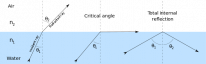
- The angle of incidence (θ1) is the angle made between the incident ray and a line that is perpendicular to the surface at the point of incidence (dotted line).
- When a ray moves from a material of higher refractive index to a material of lower refractive index, the ray is refracted away from the normal (dotted line).
Critical Angle
- The critical angle (θc) is the angle of incidence at which light is first reflected instead of refracted.
- The critical angle for normal spectacles is 41°.
Total Internal Reflection
- Total internal reflection is when the angle of incidence exceeds the critical angle.
- Light is not refracted.
- Light is reflected back into the medium with the higher refractive index.
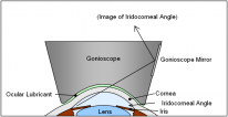
The anterior chamber angle is an important clinical structure in glaucoma. It cannot be seen directly because the light coming out of it is totally internally reflected by the corneal/air interface. A gonioscope changes the refractive index of this interface such that the angle becomes visible.
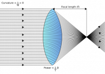
Vergence
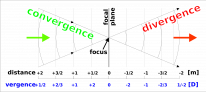
Vergence is the amount of spreading (divergence) or coming (convergence) together of light. It is measured in dioptres (D), where D is the reciprocal of the distance to the point where light rays would intersect if extended in either direction (focal length). D=1/f(m)
Converging rays have a plus vergence. Diverging rays have a minus vergence. Parallel rays have 0 vergence.
Lens Power


- A lens changes the vergence of light, whether it's the crystalline lens, spectacles, contact lenses or IOL implants.
- A plus lens converges light.
- A minus lens diverges light.
Basic Lens Formula
- U+D=V
- U → vergence of light entering the lens (object rays)
- D → vergence added to light by the lens (lens power)
- V → vergence of light leaving the lens (image rays)
Example
Light from an object 2m away is travelling to a +2D lens. At what distance is the image going to be formed?
- U= 1/2 = -0.5D
    - Light coming from a natural object is divergent (minus)
- D = +2D
- V = -0.5+2 = +1.5D
- Recall that D=1/f(m), therefore, 1/1.5 = 0.67m
- The image will form 0.67m on the other side of the lens
Where questions involve distance and dioptres, take the reciprocal to switch between the units.
Image Qualities
The image produced by a lens can be real/virtual, erect/inverted and magnified/diminished. The underlying principles of image projection are discussed in this section.
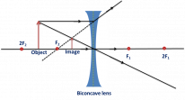
The most important thing you should know is that the image created by a minus lens (biconcave) is virtual, erect and diminished. The image created by a plus lens (biconvex) can be real or virtual, erect or inverted, and magnified or diminished; all depending on the distance of the object relative to the focal point of the lens.

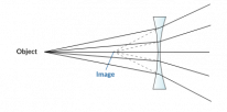
A biconcave lens will produce a diminished, erect, virtual image - irrespective of the object distance.
Object distance |
Image type |
Magnification |
Orientation |
|---|---|---|---|
Less than focal length(f) |
Virtual |
Magnified |
Erect |
Between f and 2f(2 times focal length) |
Real |
Magnified |
Inverted |
Further than 2f |
Real |
Diminished |
Inverted |
Visual Acuity Testing
Visual acuity is a measure of the clarity of vision. There are subjective and objective methods of testing. Retinoscopy is the most commonly used objective test of visual acuity. The other tests that are discussed in this section are all subjective (depend on the patient's response).
Snellen Chart
![]()
- Most commonly used test in clinics.
- Patients stand 6m away and read the letters on the chart.
- A score is given as a fraction where the numerator is the distance away from the chart:
- 20/200 = 6/60
- This means that the patient can read at 6m, what the average person can read at 60m.
- 20/20 = 6/6
- This means that the patient can read at 6m what the average patient can read at 6m.
- 20/200 = 6/60
- 6/12 (line 6) is the minimum driving requirement.
- This is crudely tested by asking the patient to read a number plate at 20m during the driving test.
LogMAR Chart
![]()
- More accurate than Snellen but mainly used in research settings.
- There are 5 letters in each row at equidistance, this accounts for the crowding phenomenon, and makes LogMAR more accurate than Snellen.
- Patients stand 4m away.
- A score between 1-0 is given where 0 is best.
- 0 LogMAR = 6/6 Snellen
- 1 LogMAR = 6/60 Snellen
- Each letter is worth 0.02 units, which are accumulated and subtracted from 1 to give the final score.
Duochrome Test

- The chart has black letters on either a red background or a green. The patient is asked to determine which background makes the letters clearer:
- No difference → no refractive error
- Red background is clearer → hyperopia
- Green background clearer → myopia
- The principle underlying this test is chromatic aberration:
- Red has a longer wavelength and focuses behind the retina.
- Green has a shorter wavelength and focuses in front of the retina.
Retinoscopy
- A retinoscope is similar to an ophthalmoscope. The key difference is that the light source of the retinoscope can be quickly moved off the visual axis.
- Retinoscopy is an objective measure of visual acuity.
- The examiner shines the light from the retinoscope and aims to observe the red retinal reflex. Different lenses are added in front of the light to achieve the perfect red reflex.
- The power of these lenses tells you the amount of refractive error.
- The direction of the red reflex against the direction of the light from the retinoscope tells you the type of refractive error:
- Myopia → red reflex moves against the direction of light
- Hyperopia → red reflex moves with the direction of light
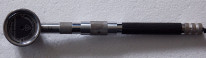
A retinoscope. By Janee, CC BY-SA 3.0, via Wikimedia Commons.
Visual Acuity in Children
Testing in Children
Situation |
Test |
|---|---|
Preverbal infants |
Keeler cards (Preferential looking) |
Preverbal children |
Cardiff cards |
Verbal but illiterate children |
Kay picture cards |
Verbal and semi-literate children (3-5years) |
Sheridan-Gardiner and Sonksen (single letter cards) |
Verbal and Literate children (>4years) |
Snellen and LogMAR |
Visual Acuity Development
Age |
Snellen Score |
Description |
|---|---|---|
Birth |
>6/60 |
Poor vision |
3 months |
6/60 |
Fixate on objects and faces |
6 months |
6/30 |
Develops colour vision |
1-2years |
6/6 |
Adult level vision |
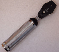
Optics of Ophthalmoscopes
Ophthalmoscopes are also known as fundoscopes because they allow you to visualise the fundus of the eye - the interior surface of the retina behind the lens. There are 2 main types of fundoscopy: direct and indirect. Direct ophthalmoscopy provides a magnified view of the central fundus. Indirect ophthalmoscopy provides a wider stereoscopic view, up to the ora serrata. It is useful in cases where the direct fundus view is obstructed by hazy media or cataracts.
Types of Fundoscopy
Characteristics |
Direct |
Indirect |
|---|---|---|
Lens |
Not required |
Required |
Image produced |
Erect and virtual |
Inverted and real |
Depth perception (stereopsis) |
Absent |
Present |
Fundus view |
Slightly beyond the centre |
All the way to the periphery and ora serrata |
Examination distance |
Close to the eye |
At arm’s length |
Magnification |
15x |
2-5x |

In indirect ophthalmoscopy, the field of view is largest in cases of high myopia and smaller in hyperopia.
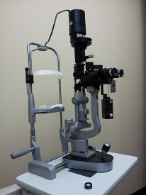
Optics of Slit Lamps
Slit lamps are the staple tool of examination in ophthalmology. They allow you to examine the ocular structures in detail. The patient is dilated during the exam. There are several different illumination techniques which allow the examiner to focus on various structures. This section will review these structures and techniques.
Diffuse Illumination

- Wide beam of light diffusely illuminating the eye and external structures.
- Used for general examination.
Direct Focal Illumination
- This is the most commonly used type of illumination.
- It focuses a beam of light directly on the part of the eye being examined.
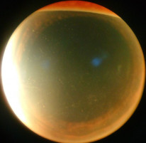
Retroillumination
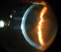
- Light is reflected back from structures to posteriorly illuminate structures in front. E.g from the iris to the cornea or the retina to the iris/lens
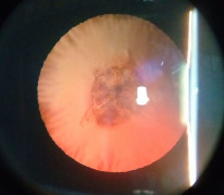
Retroillumination from the fundus showing an anterior subcapsular cataract. By Imran kabirhossain, CC BY-SA 4.0 , via Wikimedia Commons.
Specular Reflection
- Focuses the view on the corneal endothelium.
- Useful in corneal endothelial diseases such as Fuchs' endothelial dystrophy.
Sclerotic Scatter
- The beam of light from the slit lamp is projected onto the corneal limbus. This light is scattered throughout the cornea and illuminates corneal lesions.